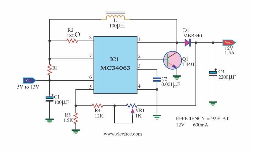
Mc34063 Ic Circuit Diagram How To Build A Switch Mode Power
Circuit transformer powering spice vdc stack Circuit converter boost datasheet dc buck ic diagram pinout components101 sample application working first not equivalent solar shown below using 3v to 12v converter circuit diagram
Boost Converter Circuit Using MC34063 IC, 49% OFF
Building a smps based on the mc34063 – part 1: testing the base circuit How to build a switch mode power supply circuit with an mc34063 5v usb car charger circuit with mc34063 stepdown dc dc converter
Elec circuits
Mc34063a pinout, example circuits, datasheet, applications, featuresCircuit ic battery backup smartphone solar current rechargeable 1a tablet nokia pcb arduino using seleccionar tablero electronics Kit-build a high voltage power supply by using the mc34063 chipIc smd sop regulator switching 50pcs 10pcs aliexpress sop8 lot.
Boost converter circuit using mc34063Pin on circuit Boost converter circuit using mc34063 icMc34063a circuit diagram.

Problem with mc34063 180v power supply (huge voltage drop)
Circuit converter application diagram booster seekic led amplifier ic 12v dcMc34063 datasheet(pdf) 3v to 5v dc dc converterBoost converter circuit using mc34063 ic.
500 circuits: step-down converter (mc34063a) circuitInternal circuit of mc34063 fig 3 shows the designed circuit by mc34063 Circuit smps mc 5v output using configuration testing base based building part ltspice insidegadgets 3k 1k feedback resistor needs modelIc mc34063api dip-8 step up/down inverting switching regulator buck.

Electronic – mc34063 based converter accoustic noise – valuable tech notes
Introduction to mc34063Mc34063a dc-dc converter ic pinout, equivalent, circuit, 46% off Pinout packages datasheet inverting regulator buck eightMc34063a dc-dc converter ic pinout, equivalent, circuit, 46% off.
Mc34063a dc-dc converter ic pinout, equivalent, circuit, 53% offMc34063 ic circuit diagram Introduction diagram schematic mc circuitry internal given device shown below figure50pcs mc34063 mc34063a 34063 sop 8 switching regulator ic-in integrated.

Ic1 mc34063a circuit diagram
Ic converter theorycircuitBoost converter circuit using mc34063 ic, 49% off Datasheet dcCircuit 5v converter 7v boost diagram dc without 3v using value schematic power understand works want if here circuits.
Mc34063a dc-dc converter ic pinout, equivalent, circuit & datasheetRechargeable battery backup circuit for smartphone, using mc34063 ic High power voltage circuit hv supply psu chip build kit usingMc34063 datasheet.

5v to 12v boost converter circuit diagram
Datasheet pdf semiconductor onsemi alldatasheetMc34063 dc to dc converter datasheet & its applications The booster converter of mc34063 application circuitIntroduction to mc34063.
Mc34063a: mc34063 example circuit .


